From Surf Wiki (app.surf) — the open knowledge base
Tube socket
Plug-in vacuum tube holder
Plug-in vacuum tube holder
Tube sockets are electrical sockets into which vacuum tubes (electronic valves) can be plugged, holding them in place and providing terminals, which can be soldered into the circuit, for each of the pins. Sockets are designed to allow tubes to be inserted in only one orientation. They were used in most tube electronic equipment to allow easy removal and replacement. When tube equipment was common, retailers such as drug stores had vacuum tube testers, and sold replacement tubes. Some Nixie tubes were also designed to use sockets.
Throughout the tube era, as technology developed, sometimes differently in different parts of the world, many tube bases and sockets came into use.{{cite web | access-date = 9 January 2013 }} Sockets are not universal; different tubes may fit mechanically into the same socket, though they may not work properly and possibly become damaged.
Tube sockets were typically mounted in holes on a sheet metal chassis and wires or other components were hand soldered to lugs on the underside of the socket. In the 1950s, printed circuit boards were introduced and tube sockets were developed whose contacts could be soldered directly to the printed wiring tracks. Looking at the bottom of a socket, or, equivalently, a tube from its bottom, the pins were numbered clockwise, starting at an index notch or gap, a convention that has persisted into the integrated circuit era.
In the 1930s, tubes often had the connection to the control grid brought out through a metal top cap on the top of the tube. This was connected by using a clip with an attached wire lead. An example would be the 6A7 pentagrid converter. Later, some tubes, particularly those used as radio frequency (RF) power amplifiers or horizontal deflection amplifiers in TV sets, such as the 6DQ6, had the plate or anode lead protrude through the envelope. In both cases this allowed the tube's output circuitry to be isolated from the input (grid) circuit more effectively. In the case of the tubes with the plate brought out to a cap, this also allowed the plate to run at higher voltages (over 26,000 volts in the case of rectifiers for color television, such as the 3A3, as well as high-voltage regulator tubes.) A few unusual tubes had caps for both grid and plate; the caps were symmetrically placed, with divergent axes.

The first tubes
The earliest tubes, like the Deforest Spherical Audion from , used the typical light bulb Edison socket for the heater, and flying leads for the other elements. Other tubes directly used flying leads for all of their contacts, like the Cunningham AudioTron from 1915, or the Deforest Oscillion. Type C6A xenon thyratrons, used in servos for the U.S. Navy Stable Element Mark 6, had a mogul screw base and L-shaped stiff wires at the top for grid and anode connections. Mating connectors were machined pairs of brass blocks with clamping screws, attached to flying leads (free hanging).
Early bases
Before alternating current (AC) line/mains-powered radios were developed, some four-pin tubes (in particular, the very common UX-201A ('01A)) had a bayonet pin on the side of a cylindrical base. The socket used that pin for retaining the tube; insertion finished with a slight clockwise turn. Leaf springs, essentially all in the same plane, pressed upward on the bottoms of the pins, also keeping the bayonet pin engaged.
The first hot-cathode CRT, the Western Electric 224-B, had a standard four-pin bayonet base, and the bayonet pin was a live connection. (Five effective pins: It was an electrostatic-deflection gas-focused type, with a diode gun and single-ended deflection. The anode and the other two plates were common.)
An early exception to these types of bases is the Peanut 215, which instead of using prongs had a tiny bayonet base with four drop-like contacts. Another exception is the European Side Contact series commonly known as P, which instead of using a prong, relied on side contacts at 90 degrees from the tube axis with four to twelve contacts.
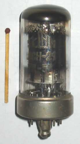
Octal {{anchor|Octal base}}
In April 1935, the General Electric Company introduced a new eight-pin tube base with their new metal envelope tubes. The new base became known as the octal base. The octal base provided one more conductor with a smaller overall size of the base than the previous line of U. S. tube bases which had provided a maximum of seven conductors. Octal bases, as defined in IEC 60067, diagram IEC 67-I-5a, have a 45-degree angle between pins, which form a 17.45 mm diameter circle around a 7.82 mm diameter keyed post (sometimes called a spigot) in the center. Octal sockets were designed to accept octal tubes; the rib in the keyed post fitted an indexing slot in the socket so the tube could only be inserted in one orientation.
When used on metal tubes, pin 1 was always reserved for a connection to the metal shell, which was usually grounded for shielding purposes. This reservation prevented tubes such as the 6SL7/6SN7 dual triodes from being issued with metal envelopes, as such valves need three connections (cathode, grid, anode) for each triode (making six total) plus two connections for the paralleled heaters. The octal base soon caught on for glass tubes, where the large central post could also house and protect the "evacuation tip" of the glass tube. The eight available pins allowed more complex tubes than before, such as dual triodes, to be constructed. The glass envelope of an octal base tube was cemented into a bakelite or plastic base with a hollow post in the center, surrounded by eight metal pins. The wire leads from the tube were soldered into the pins, and the evacuation tip was protected inside the post.
Matching plugs were also manufactured that let tube sockets be used as eight-pin electrical connectors; bases from discarded tubes could be salvaged for this purpose. Octal sockets were used to mount other components, particularly electrolytic capacitor assemblies and electrical relays; octal-mount relays are still common.
Most octal tubes following the widespread European designation system have penultimate digit "3" as in ECC34 (full details in the Mullard–Philips tube designation article). It is also called International Octal. There is a different, totally obsolete, pre-world-war-II German octal type. The Mazda octal is larger (Octal-8 GB, K8B, MO).
Octal and miniature tubes are still in use in tube-type audio hi-fi and guitar amplifiers. Relays were historically manufactured in a vacuum tube form, and industrial-grade relays continue to use the octal base for their pinout. File:6P3S.jpg|An octal base tube, Soviet 6Π3C, similar to the 6L6. File:6SN7 octal base.jpg|Octal base of a 6SN7 File:Vacuum tube octal socket.jpg|An octal socket
Loctal
A variant of the octal base, the B8G loctal base or lock-in base (sometimes spelled "loktal" — trademarked by Sylvania), was developed by Sylvania for ruggedized applications such as automobile radios. Along with B8B (a British designation out of date by 1958), these eight-pin locking bases are almost identical and the names usually taken as interchangeable (although there are some minor differences in specifications, such as spigot material and spigot taper, etc.). The pin geometry was the same as for octal, but the pins were thinner (although they will fit into a standard octal socket, they wobble and do not make good contact), the base shell was made of aluminium, and the center hole had an electrical contact that also mechanically locked (hence "loctal") the tube in place. Loctal tubes were only used widely by a few equipment manufacturers, most notably Philco, which used the tubes in many table radios. Loctal tubes have a small indexing mark on the side of the base skirt; they do not release easily from their sockets unless pushed from that side. Because the pins are actually the Fernico or Cunife lead-out wires from the tube, they are prone to intermittent connections caused by the build-up of electrolytic corrosion products due to the pin being of a different metallic composition to the socket contact.
The loctal tube's structure was supported directly by the connecting pins passing through the glass "button" base. Octal tube structures were supported on a glass "pinch", formed by heating the bottom of the envelope to fusing temperature, then squeezing the pinch closed. Sealing the pinch embedded the connecting wires in the pinch's glass and gave a vacuum-tight seal. The connecting wires then passed through the hollow base pins, where they were soldered to make permanent connections.
Loctal tubes had shorter connecting lengths between the socket pins and the internal elements than did their octal counterparts. This allowed them to operate at higher frequencies than octal tubes. The advent of miniature "all-glass" seven- and nine-pin tubes overtook both octals and loctals, so the loctal's higher-frequency potential was never fully exploited.
Loctal tube type numbers in the USA typically begin with "7" (for 6.3-volt types) or "14" for 12.6-volt types. This was fudged by specifying the heater voltage as nominally 7 or 14 volts so that the tube nomenclature fitted. Battery types (mostly 1.4-volt) are coded "1Lxn", where x is a letter and "n" a number, such as "1LA4". Russian loctals end in L, e.g. 6J1L. European designations are ambiguous; all B8G loctals have numbers either in the range:
- 20–29, (such as EBL21, ECH21, EF22) except for early tubes in the series: DAC21, DBC21, DCH21, DF21, DF22, DL21, DLL21, DM21 which have either B9G or octal bases, the change to Sylvania's locktal standard coming in 1942
- or 50–59 (special bases, including the European 9-pin lock-in base), but other types are in the same range (e.g. while EF51 is B8G loctal, the EF55 is 9-pin loctal, B9G, and the EL51 has a side-contact P8A base).
Other loctals
- Nine-pin loctal bases, B9G, include the 1938 Philips EF50, EL60 and some type numbers in the European 20–29 and 50–59 range;
- There is a different "loctal Lorenz" in the Mullard–Philips tube designation .
Miniature tubes
Efforts to introduce small tubes into the marketplace date from the 1920s, when experimenters and hobbyists made radios with so-called peanut tubes like the Peanut 215 mentioned above. Because of the primitive manufacturing techniques of the time, these tubes were too unreliable for commercial use.
RCA announced new miniature tubes in Electronics magazine, which proved reliable. The first ones, such as the 6J6 ECC91 VHF dual triode, were introduced in 1939. The bases commonly referred to as "miniature" are the seven-pin B7G type, and the slightly later nine-pin B9A (Noval). The pins are arranged evenly in a circle of eight or ten evenly spaced positions, with one pin omitted; this allows the tube to be inserted in only one orientation. Keying by omitting a pin is also used in 8- (subminiature), 10-, and 12-pin (Compactron) tubes (a variant 10-pin form, "Noval+1", is basically a nine-pin socket with an added center contact).
As with loctal tubes, the pins of miniature tube are stiff wires protruding through the bottom of the glass envelope which plug directly into the socket. However, unlike all their predecessors, miniature tubes are not fitted with separate bases; the base is an integral part of the glass envelope. The pinched-off air evacuation nub is at the top of the tube, giving it its distinctive appearance. More than one functional section can be included in a single envelope; a dual triode configuration is particularly common. Seven- and nine-pin tubes were common, though miniature tubes with more pins, such as the Compactron series, were later introduced, and could fit up to three amplifying elements. Some miniature tube sockets had a skirt that mated with a cylindrical metal electrostatic shield that surrounded the tube, fitted with a spring to hold the tube in place if the equipment was subject to vibration. Sometimes the shield was also fitted with thermal contacts to transfer heat from the glass envelope to the shield and act as a heat sink, which was considered to improve tube life in higher power applications.
Electrolytic effects from the differing metal alloys used for the miniature tube pins (usually Cunife or Fernico) and the tube base could cause intermittent contact due to local corrosion, especially in relatively low current tubes, such as were used in battery-operated radio sets. Malfunctioning equipment with miniature tubes can sometimes be brought back to life by removing and reinserting the tubes, disturbing the insulating layer of corrosion.
Miniature tubes were widely manufactured for military use during World War II, and also used in consumer equipment. The Sonora Radio and Television Corporation produced the first radio using these miniature tubes, the "Candid", in April 1940. In June 1940 RCA released its battery-operated Model BP-10, the first superheterodyne receiver small enough to fit in a handbag or coat pocket. This model had the following tube lineup: 1R5 — pentagrid converter; 1T4 — I.F. amplifier; 1S5 — Detector/AVC/AF Amplifier; 1S4 — Audio Output. The BP-10 proved so popular that Zenith, Motorola, Emerson, and other radio manufacturers produced similar pocket radios based on RCA's miniature tubes. Several of these pocket radios were introduced in 1941 and sold until the suspension of radio production in April 1942 for the duration of World War II.
After the war miniature tubes continued to be manufactured for civilian use, regardless of any technical advantage, as they were cheaper than octals and loctals.
Miniature seven-pin base
The B7G (or "small-button" or "heptal") seven-pin miniature tubes are smaller than Noval, with seven pins arranged at 45-degree spacing in a 9.53 mm (3/8th inch) diameter arc, the "missing" pin position being used to position the tube in its socket (unlike octal, loctal and rimlock sockets). Examples include the 6AQ5/EL90 and 6BE6/EK90. European tubes of this type have numbers 90-99, 100-109, 190-199, 900-999. A few in the 100-109 series have unusual, non-B7G bases, e.g., Wehrmacht base.
Noval base
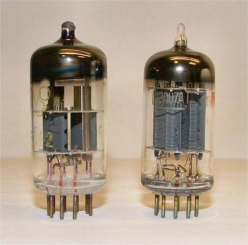
The nine-pin miniature Noval B9A base, sometimes called button 9-pin, B9-1, offered a useful reduction in physical size compared to previous common types, such as octal (especially important in TV receivers where space was limited), while also providing a sufficient number of connections (unlike B7G) to allow effectively unrestricted access to all the electrodes, even of relatively complex tubes such as double triodes and triode-hexodes. It could also provide multiple connections to an electrode of a simpler device where useful, as in the four connections to the grid of a conventional grounded-grid UHF triode, e.g., 6AM4, to minimise the deleterious effects of lead inductance on the high-frequency performance.
This base type was used by many of the United States and most of the European tubes, e.g., 12AX7-ECC83, EF86 and EL84, produced commercially towards the end of the era before transistors largely displaced their use.
The IEC 67-I-12a specification calls for a 36-degree angle between the nine pins of 1.016 mm thickness, in an arc of diameter 11.89 mm.
European tubes of this type have numbers 80-89, 180-189, 280-289, 800-899, 8000-8999.
Duodecar base
The Duodecar B12C base (IEC 67-I-17a) has 12 pins in a 19.1 mm diameter circle and dates from 1961. It was also called the Compactron T-9 construction/E12-70 base It is generally similar in form to a Noval socket, but larger. In the center is a clearance hole for a tube evacuation pip, which is typically on the bottom of a Compactron tube. (It should not be confused with the similar-sounding but differently sized Duodecal B12A base.)
Rimlock base
The Rimlock (B8A) base is an eight-pin design with a pin circle diameter close to Noval, and uses a nub on the side of the envelope to engage with a guide and retaining spring in the socket wall. This provides pin registration (since the pins are equi-spaced) and also a fair degree of retention. Early tubes with this base type typically had a metal skirt around the lower ~15mm of the envelope to match the socket wall, and this offered a degree of built-in screening, but these were fairly soon replaced by "skirtless" versions, which had a characteristic widening in the glass to compensate physically for the absence of the skirt. In the European naming scheme, rimlock tubes are numbered in the ranges 40-49, 110-119 (with exceptions), and 400-499, e.g., EF40. Although virtually unknown elsewhere, this was a very common base type in European radios of the late 1940s through the 1950s, but was eventually displaced by the ubiquitous B7G and Noval (B9A) base types.
UHF tubes

By 1935 new tube technologies were required for the development of radar and telecommunications. UHF requirements severely limited the existing tubes, so radical ideas were implemented which affected how these tubes connected to the host system. Two new bases appeared, the acorn tube and the lighthouse tube, both solving the same problems but with different approaches. Thompson, G.M. Rose, Saltzberg and Burnside from RCA created the acorn tube by using far smaller electrodes, with radial short connections. A different approach was taken by the designers of the lighthouse tube, such as the octal-base 2C43, which relied on using concentric cylindrical metal contacts in connections that minimized inductance, thus allowing a much higher frequency.
Nuvistors were very small, reducing stray capacitances and lead inductances. The base and socket were so compact that they were widely used in USA UHF TV and VHF radio tuners for a few years. They could also be used in small-signal applications at lower frequencies, as in the Ampex MR-70, a costly studio tape recorder whose entire electronics section was based on nuvistors.
Other socket styles
There are many other socket types, of which a few are:
- Decal B10B base (IEC 67-I-41a) 10 pins with 1.02 mm diameter in an 11.89 mm diameter circle, e.g. PFL200
- Decar B10G base (IEC E10-73) A 10th pin added to the center of a standard 9-pin miniature base, e.g. 6C9
- Magnoval B9D base (IEC 67-I-36a) 9 pins with 1.27 mm diameter in a 17.45 mm pin circle diameter arc, e.g. EL503, EL509, PD500, etc. - not to be confused with...
- Novar B9E base, 9 pins with 1.02 mm diameter in a 17.45 mm pin circle diameter arc, one of several Compactron types, which looks similar to Magnoval (but a Novar tube in a Magnoval socket will not make good pin contact, and a Magnoval tube in a Novar socket may damage the socket).
- Sub-Magnal B11A base (American), 11-pins. Also used as industrial relay socket and HV power supplies. Amphenol / WirePro (WPI) / Eaton 78-series, Socket (female) part number: 78-S-11. Matching Plug (male) is part number: 86-CP-11
- Neo Eightar base (IEC 67-I-31a) 8 pins in a 15.24 mm diameter circle
- 5-pin sub-miniature wire-ended B5A base (no socket used; e.g. EA76)
A remarkably wide variety of tube and similar sockets is listed and described, with some informal application notes, at a commercial site, Pacific T.V., including nuvistor, eight-pin subminiature, vidicon, reflex klystron, nine-pin octal-like, 10-pin miniature (two types), 11-pin sub-magnal, diheptal 14-pin, and many display tubes such as Nixies and vacuum fluorescent types (and even more). As well, each socket has a link to a clear, high-quality picture.
Some subminiature tubes with flexible wire leads all exiting in the same plane were connected by subminiature inline sockets.
Some low-power reflex klystrons such as the 2K25 and 2K45 had small-diameter rigid coaxial outputs parallel to octal base pins. To accommodate the coax, one contact was replaced by a clearance hole.
Vacuum tubes for high-power applications often required custom socket designs. A jumbo four-prong socket was used for various industrial tubes. A specialized seven-pin socket (Septar or B7A), with all pins in a circle with one pin wider than the others, was used for transmitting tubes. Subminiature tubes with long wire leads, introduced in the 1950s, were often soldered directly to printed circuit boards. Sockets were made for early transistors, but quickly fell out of favor as transistor reliability became established. This also happened with early integrated circuits; IC sockets later became used only for devices that may need to be upgraded.
Summary of base details
| Common name | Standard Name | Other names | Base Pins | Pin Layout | Pin thickness | Specification | Period | Examples | European / Pro Electron numeric range | Pee-Wee | Mazda subminiature | European 3-pin | UV4 | UX4 | B4 | UY5 | |||||||||||||||||||||||
|---|---|---|---|---|---|---|---|---|---|---|---|---|---|---|---|---|---|---|---|---|---|---|---|---|---|---|---|---|---|---|---|---|---|---|---|---|---|---|---|
| UX5 | B5 | UX6 | B7 | UX7 | Septar | Miniature 7-Pin | Transcontinental | Octal | Mazda Octal | Loctal | Rimlock | Loctal-9pin | Noval (Miniature 9-pin) | Magnoval | Novar | Decal | Decar | Sub-Magnal | DuoDecal | Duodecar | Nuvistor | Nuvistor | |||||||||||||||||
| B3A | US Pee Wee 3p | 3 | 08.7mm triangle with pins 1&3 closest | 2.36mm | 1937 - | ZA1004 | - | ||||||||||||||||||||||||||||||||
| B3G | European special all-glass miniature | 3 (+top) | 06.0mm line with 3mm spacing | 1mm | Mazda | 1937 - | D1, EA50 | - | |||||||||||||||||||||||||||||||
| H3A | British 3-pin, Eu-3 | ||||||||||||||||||||||||||||||||||||||
| (or B4, ignoring pin 4) | 3 | 16mm isosceles triangle, greatest distance between pins 2 & 3 | 3.2mm | 1920s to early 1930s | |||||||||||||||||||||||||||||||||||
| (superseded by Octal and P8) | RE4120, 1832 | - | |||||||||||||||||||||||||||||||||||||
| B4B | WD-4-Pin | 4 | 09.8mm rectangle with large pin 2 (usually anode) | 2.3mm x3 | |||||||||||||||||||||||||||||||||||
| 3.1mm (pin 2) | 1914 - 1920's | ||||||||||||||||||||||||||||||||||||||
| (superseded by UX4) | WD-11 | - | |||||||||||||||||||||||||||||||||||||
| U4A | American 4-pin base with or without bayonet pin | 4 | 11.9mm rectangle with thicker pins 1 & 4. | ||||||||||||||||||||||||||||||||||||
| Superseded the UV4 base | 3.2mm (pins 2&3) | ||||||||||||||||||||||||||||||||||||||
| 4.0mm (pins 1&4) | A4-10 | 1920s - 1930s | |||||||||||||||||||||||||||||||||||||
| (mostly superseded by Octal, but still used for some currently produced directly heated triodes) | A-P Oscillator (1920), 2A3, 300B, B405, X99, WW313A (1938), 866A | - | |||||||||||||||||||||||||||||||||||||
| A4A | British 4-pin, A4, European 4-pin | 4 | 16.25mm kite | 3.2mm | 1915 to early 1930s | ||||||||||||||||||||||||||||||||||
| (superseded by Octal and P8) | B405, BL2, R-type | - | |||||||||||||||||||||||||||||||||||||
| U5A | |||||||||||||||||||||||||||||||||||||||
| B5C | US 5-contact | ||||||||||||||||||||||||||||||||||||||
| American Small 5-pin, USS5 | 5 | 19mm (3/4") circle, | |||||||||||||||||||||||||||||||||||||
| 3x60° between pins 1,2 and 4,5,1, | |||||||||||||||||||||||||||||||||||||||
| 2x90° between pins 2,3,4 Note: some databooks and websites use UX and UY seemingly interchangeably. Yet one has equal-sized pins and the other has pins 1&5 thicker -- | 3.? | A5-11 | 1920s | UY227, 2E22, 1D4, 49, 807 | - | ||||||||||||||||||||||||||||||||||
| O5A | British 5-pin, European 5 -pin, Europa | 5 | 16.25mm kite; B4 with central 5th pin added | ||||||||||||||||||||||||||||||||||||
| a B5 socket will accept European 3-pin (H3A) and 4-pin (A4A) tubes | 3.2mm | 1928 to early 1930s | |||||||||||||||||||||||||||||||||||||
| (superseded by Octal and P8) | B443 | - | |||||||||||||||||||||||||||||||||||||
| U6A | US 6-pin | 6 | 19mm (3/4") circle, | ||||||||||||||||||||||||||||||||||||
| 6x60° | 3.2mm x4, 3.9mm (pins 1 & 6) | 1930's | |||||||||||||||||||||||||||||||||||||
| (superseded by Octal) | 1F6, 2A5 | - | |||||||||||||||||||||||||||||||||||||
| M7A | British 7-pin | 7 | 23.1mm x 18.2mm oval | 3.2mm | 1930s (ultimately superseded by Octal) | AC3/Pen, TDD4, AL60, 18013 | - | ||||||||||||||||||||||||||||||||
| U7A | US 7-pin small | 7 | 19mm (3/4") circle, | ||||||||||||||||||||||||||||||||||||
| 3x52°,4x51° | 3.2mm x5, | ||||||||||||||||||||||||||||||||||||||
| 3.9mm (pins 1&7) | 1930's | ||||||||||||||||||||||||||||||||||||||
| (superseded by Octal) | 2B7, 6A7 | - | |||||||||||||||||||||||||||||||||||||
| B7A | 7 | 26mm circle | 2.7mm x6, 4.0mm | 6C33, 829B, 3C33, 3E29, 832A, 5894, FU-29, GZ67-C | |||||||||||||||||||||||||||||||||||
| B7G | Miniature, Button, Mi-7 | 7 | 09.53mm (3/8") circle, | ||||||||||||||||||||||||||||||||||||
| 6x45° then 90° between pins 7 & 1 | 1.016mm | IEC 67-I-10a | 1939 - present | 1S4/DL91, 6AQ5, 6X4 | 90-99, some 100-109, 190-199, 900-999 | ||||||||||||||||||||||||||||||||||
| P8A | P-Type, Ct8, Philips 8, Side-contact 8 | 8 | 29.5mm circle of side-contact pins, | ||||||||||||||||||||||||||||||||||||
| 3x30° (pins 1-4), | |||||||||||||||||||||||||||||||||||||||
| 5x54° | Side-contact | Philips | 1930s | AL3 | 1-9 usually | ||||||||||||||||||||||||||||||||||
| K8A | IO, International Octal, A08, American octal base, Oc-8 | 8 | 17.45mm (11/16") circle, equal 45° spacing, 7.8mm spigot | 2.36mm | originally: RCA IEC 67-I-5a | 1935 - present | 6CA7/EL34, 6L6/5881, 6SN7, 6V6GT, KT63/KT66/KT77/KT88/KT90, 6550, 7591 | 3G, 30-39, 300-399 | |||||||||||||||||||||||||||||||
| K8B | title=Base Mazda Octal | url=http://www.r-type.org/static/basemo.htm | publisher=The National Valve Museum | access-date=7 January 2013}} | 8 | title=ATP4 tube | url=http://amateurtele.com/index.php?nav=1&artikel=101 | publisher=The AmateurTele.com | access-date=10 February 2015}} 8.7mm spigot | 2.36mm | Mazda | 1938 - ? | |||||||||||||||||||||||||||
| (short-lived) | ARP12, AR8, SP42, ATP4 | - | |||||||||||||||||||||||||||||||||||||
| B8G | |||||||||||||||||||||||||||||||||||||||
| or B8B | 8-pin Loktal, Lo-8, Locking Octal | 8 | 17.45mm (11/16") circle, equal 45° spacing, 6.7mm spigot | 1.3mm | Sylvania | 1939 | 1LN5, EF22, ECH71 | 20-29 and some others | |||||||||||||||||||||||||||||||
| B8A | European 8-pin Miniature base, Ri-8 | 8 | 11.5mm (0.453") circle, 45° | 1.015mm | IEC 67-I-11b | 1940s | |||||||||||||||||||||||||||||||||
| quickly edged-out by Noval, etc | 6CU7/ECH42,EL41 | 40-49 | |||||||||||||||||||||||||||||||||||||
| B9G | 9-pin Loctal, Lo-9 | 9 | 21.0mm (13/16") circle, equal 40° spacing, | ||||||||||||||||||||||||||||||||||||
| spigot connected to can | 1.3mm | Philips | 1938 | ||||||||||||||||||||||||||||||||||||
| announced Sept. 1938 and available to Pye; general availability early 1939. | EC52 EF50 EF54 EL60 | 50-60 with some exceptions | |||||||||||||||||||||||||||||||||||||
| B9A | American Small Button, Button 9-pin | 9 | 11.89mm (15/32") circle, | ||||||||||||||||||||||||||||||||||||
| 8x36° then 72° spacing between pins 9 & 1 | 1.016mm | IEC 67-I-12aJEDEC E9-1 | 1948 - present (still very popular) | 12AX7/ECC83, 6BQ5/EL84 | 80-89, 180-189, 800-899 | ||||||||||||||||||||||||||||||||||
| B9D | 9 | 17.45mm (11/16") circle, | |||||||||||||||||||||||||||||||||||||
| 8x36° then 72° spacing between pins 9 & 1 | 1.27mm | IEC 67-I-36aJEDEC E9-23 | 1960s-1970s | ||||||||||||||||||||||||||||||||||||
| died out when TVs went fully solid-state | E55L, ED500, PL504 | 500-599 | |||||||||||||||||||||||||||||||||||||
| B9E | 9-pin compactron | 9 | 17.45mm (11/16") circle, 9x36° then gap between pins 9 & 1 | ||||||||||||||||||||||||||||||||||||
| Note: Novar sockets can be damaged by inserting Magnoval tubes | 1.02mm | JEDEC E9-65JEDEC E9-89 | 1959 - | ||||||||||||||||||||||||||||||||||||
| limited use; mainly TV horiz. output, damper | 6JF6, 22JG6A, 7868 | - | |||||||||||||||||||||||||||||||||||||
| B10B or B10C? often incorrectly stated | Dekal | 10 | 11.89mm (15/32") circle, | ||||||||||||||||||||||||||||||||||||
| 9x34° then 54° gap between pins 10 & 1 | 1.016mm | IEC 67-I-41a JEDEC E10-61 | 1960s - 1970s | PFL200, ECC2000, ECH200, PCF201 | 200-299 | ||||||||||||||||||||||||||||||||||
| 2000 | |||||||||||||||||||||||||||||||||||||||
| B10G | Dekar | 10 | 11.89mm (15/32") circle as Noval, with additional center pin | 1.016mm | Sylvania | ||||||||||||||||||||||||||||||||||
| JEDEC E10-73 | Mid-Late 1960s | 6C9, 17C9 | |||||||||||||||||||||||||||||||||||||
| Y10A | G10A (G8A tubes fit with pins 6 & 10 unused) | 10 | 28mm circle, 2 groups of 5 pins with two gaps | AZ11, EC156 | |||||||||||||||||||||||||||||||||||
| B11A | Magnal, B11 | 11 | 17.45mm (11/16") circle as Octal | 1.27mm | RCA? | 1940s to present | |||||||||||||||||||||||||||||||||
| B12A | Duodekal, B12 | 12 | 27mm (1.063") circle, | ||||||||||||||||||||||||||||||||||||
| 30° angles | 2.36mm | B12-43 | 1950s - 1970s | DG7-31, E1T, MW61-80 | - | ||||||||||||||||||||||||||||||||||
| B12C | 12-Pin-Compactron, E12-70, E12-74 | 12 | 19.1mm (3/4") circle, | ||||||||||||||||||||||||||||||||||||
| 11x 27.7° then gap between pins 12 & 1 | 1.02mm | E12-70(T9)E12-74(T12) | 1960s - 1970s | 1BY2, 6BD11, 12BT3 | - | ||||||||||||||||||||||||||||||||||
| E5-65 | 5 | only pins 2, 4, 8 10, 12 used from Twelvar | E5-65 | 8393 | |||||||||||||||||||||||||||||||||||
| B12K | Twelvar E7-83, E12-64, E12-65 | 12 | 11.2mm circular envelope with mixed-spacing field of pins | IEC 67-I-17a JEDEC E12-64(5/12) | 1959 - | 7586, 6DV4, 6DV8, 13CW4 | - |
References
References
- "Tube Bases". Frank's Electron Tube Pages.
- Stone, Howard. "Deforest Spherical Audion". Stone Vintage Radio Museum.
- Stone, Howard. "Cunningham Tubular Audio Tron". Stone Vintage Radio Museum.
- Stone, Howard. "Deforest Oscillion 250 W Transmitting Tube". Stone Vintage Radio Museum.
- "C6A".
- Editors, [https://worldradiohistory.com/Archive-Radio-Engineering/30s/1935/Radio-Engineering-1935-04.pdf "Metal Tubes for Receivers"], ''Radio Engineering'', April 1935, pp. 18 - 19
- G. F. Metcalf, J. E. Beggs, [https://worldradiohistory.com/Archive-Electronics/30s/Electronics-1935-05.pdf "All-metal receiving tubes, the manufacturing technique"], ''Electronics'', May 1935, pp. 149 - 150
- Editors, [https://worldradiohistory.com/Archive-Electronics/30s/Electronics-1935-09.pdf "Making Metal Tubes"], ''Radio Engineering'', Sept. 1935, pp. 31, 34
- IEC 60067: "Dimensions of electronic tubes and valves. IEC dimensions" (1966). Also published as BS 448-1:1981.
- Schmid, Kurt. "R-390A plug-in multi-section electrolytic capacitor kit". Schmid-Mainz.
- A socket similar to the standard otcal but with 11 pins also exists, and is also called "octal". It is an industry standard, developed mainly for industrial 3-phase relays (3PDT or TPDT) in order to accommodate three changeover contacts. It was also used in some older power supplies but was never used for tubes.
- "Amperite {{!}} Time Delay Relays {{!}} Flashers {{!}} Controlling Devices {{!}} Relay Requirements".
- "Advantages of a Full Featured, Octal 700 Series Relay". Magnecraft.
- "Amperite Relay Catalog". Amperite.
- (1958). "Radio Valve Data". Iliffe $ Sons Ltd.
- "Sylvania Type 7A8".
- "DAC21".
- [http://www.stonevintageradio.com/images/573.jpg Photo of 1920s era peanut tube.]
- [http://www.r-type.org/exhib/aaa0399.htm The National Valve Museum: 6J6]
- Schiffer, Michael Brian. (1992). "The Portable Radio in American Life". University of Arizona Press.
- [http://www.nostalgiaair.org/PagesByModel/428/M0015428.pdf Schematic of RCA Model BP-10]
- [http://vintage-electronics.com/photos/1183.JPG Photo of RCA Model BP-10]
- (April 1945). "Miniature Radio Tubes". Radio Age.
- Sylvania Receiving Tubes Technical Manual, 14th Edition
- (1994). "History of Electron Tubes". IOS Press.
- [http://www.r-type.org/pdfs/2c43.pdf 2C43 data sheet]
- "Pacific T.V. - Vacuum Tube Sockets".
- "Philips Data Handbook: Electron Tubes, Part 4", April 1969l
- "Abbildungen - Figures".
- "Appendix - Figures". KyteLabs.
- "Pee Wee 3p". Frank Philipse.
- "Base B3G". The National Valve Museum.
- "EA50 Signal Diode".
- (1958). ""Miniwatt" Technical Data". The "Miniwatt" Electronics Division of Philips Electrical Industries Pty. Limited.
- "A-P_Oscillator".
- "Base B4".
- (1958). ""Miniwatt" Technical Data". The "Miniwatt" Electronics Division of Philips Electrical Industries Pty. Limited.
- "807, Tube 807; Röhre 807 ID3358, Beam Power Tube". radiomuseum.org.
- "Base B5".
- "Base UX6". The National Valve Museum.
- "Base B7". The national Valve Museum.
- Philipse, Frank. "Frank's Electron tube Pages - Tube Bases".
- "Base Mazda Octal". The National Valve Museum.
- "ATP4 tube". The AmateurTele.com.
- "Appendix - Figures". KyteLabs.
- "Base B8B". The National Valve Museum.
- "Base B9G".
- Dekker, Ronald. "EF50 - The Development of the All-Glass Valve.".
- Prakke, F.. (May 1939). "A New "All-Glass" Valve Construction". The Wireless Engineer.
- (2011-02-17). "Novar vs Magnoval Vacuum Tube Sockets".
- "Base B10B". The National Valve Museum.
- "PCF201".
- (2014-02-19). "KyteLabs InfoBase - Electron Tubes & Valves Data".
- "Nuvistor 13CW4". Tube Data.
This article was imported from Wikipedia and is available under the Creative Commons Attribution-ShareAlike 4.0 License. Content has been adapted to SurfDoc format. Original contributors can be found on the article history page.
Ask Mako anything about Tube socket — get instant answers, deeper analysis, and related topics.
Research with MakoFree with your Surf account
Create a free account to save articles, ask Mako questions, and organize your research.
Sign up freeThis content may have been generated or modified by AI. CloudSurf Software LLC is not responsible for the accuracy, completeness, or reliability of AI-generated content. Always verify important information from primary sources.
Report