From Surf Wiki (app.surf) — the open knowledge base
Wave soldering
Electronics soldering process
Electronics soldering process

Wave soldering is a bulk soldering process used in printed circuit board manufacturing. The circuit board is passed over a pan of molten solder in which a pump produces an upwelling of solder that looks like a standing wave. As the circuit board makes contact with this wave, the components become soldered to the board. Wave soldering is used for both through-hole printed circuit assemblies, and surface mount. In the latter case, the components are glued onto the surface of a printed circuit board (PCB) by placement equipment, before being run through the molten solder wave. Wave soldering is mainly used in soldering of through hole components.
As through-hole components have been largely replaced by surface mount components, wave soldering has been supplanted by reflow soldering methods in many large-scale electronics applications. However, there is still significant wave soldering where surface-mount technology (SMT) is not suitable (e.g., large power devices and high pin count connectors), or where simple through-hole technology prevails (certain major appliances).
Wave solder process

There are many types of wave solder machines; however, the basic components and principles of these machines are the same. The basic equipment used during the process is a conveyor that moves the PCB through the different zones, a pan of solder used in the soldering process, a pump that produces the actual wave, the sprayer for the flux and the preheating pad. The solder is usually a mixture of metals. A typical leaded solder is composed of 50% tin, 49.5% lead, and 0.5% antimony.{{Cite book|title=Manufacturing Processes Reference Guide
Fluxing
Flux in the wave soldering process has a primary and a secondary objective. The primary objective is to clean the components that are to be soldered, principally any oxide layers that may have formed. There are two types of flux, corrosive and noncorrosive. Noncorrosive flux requires precleaning and is used when low acidity is required. Corrosive flux is quick and requires little precleaning, but has a higher acidity.
Preheating
Preheating helps to accelerate the soldering process and to prevent thermal shock.{{Cite book|title=Soldering Processes and Equipment
Cleaning
Some types of flux, called "no-clean" fluxes, do not require cleaning; their residues are benign after the soldering process.{{Cite book|title=Principles of Soldering
Finish and quality
Quality depends on proper temperatures when heating and on properly treated surfaces.
| Defect | Possible causes | Effects |
|---|---|---|
| Cracks | Mechanical Stress | Loss of Conductivity |
| Cavities | Contaminated surface | Reduction in strength |
| Wrong solder thickness | Wrong solder temperature | Susceptible to stress |
| Poor Conductor | Contaminated solder | Product Failures |
Solder types
Different combinations of tin, lead and other metals are used to create solder. The combinations used depend on the desired properties. The most popular combinations are SAC (Tin(Sn)/Silver(Ag)/Copper(Cu)) alloys for lead-free processes and Sn63Pb37 (Sn63A) which is a eutectic alloy consisting of 63% tin and 37% lead. This latter combination is strong, has a low melting range, and melts and sets quickly (i.e., no 'plastic' range between the solid and molten states like the older 60% tin / 40% lead alloy). Higher tin compositions give the solder higher corrosion resistances, but raise the melting point. Another common composition is 11% tin, 37% lead, 42% bismuth, and 10% cadmium. This combination has a low melting point and is useful for soldering components that are sensitive to heat. Environmental and performance requirements also factor into alloy selection. Common restrictions include restrictions on lead (Pb) when RoHS compliance is required and restrictions on pure tin (Sn) when long term reliability is a concern.
Effects of cooling rate
It is important that the PCBs be allowed to cool at a reasonable rate. If they are cooled too fast, then the PCB can become warped and the solder can be compromised. On the other hand, if the PCB is allowed to cool too slowly, then the PCB can become brittle and some components may be damaged by heat. The PCB should be cooled by either a fine water spray or air cooled to decrease the amount of damage to the board.
Thermal profiling
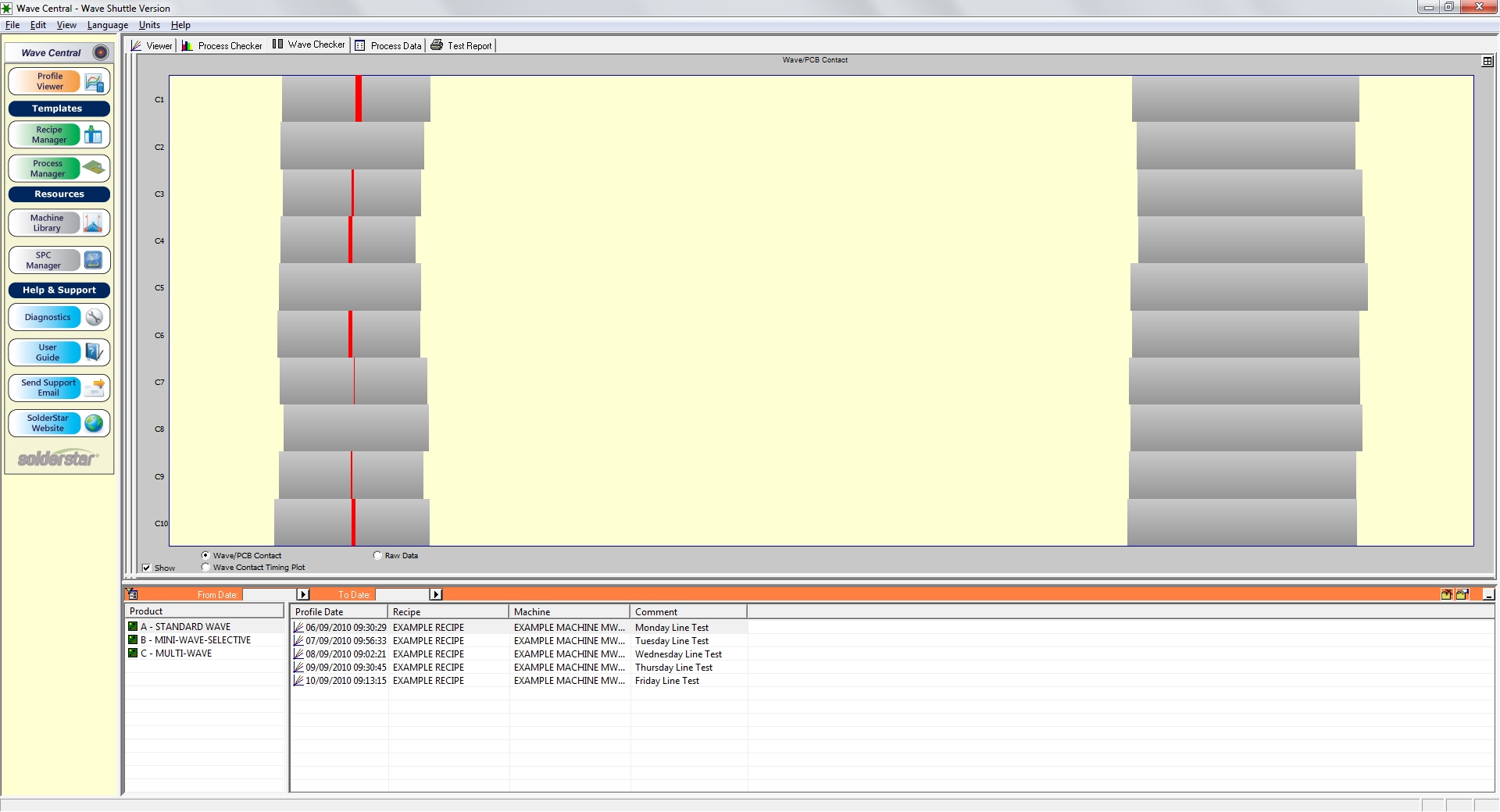
Thermal profiling is the act of measuring several points on a circuit board to determine the thermal excursion it takes through the soldering process. In the electronics manufacturing industry, SPC (Statistical Process Control) helps determine if the process is in control, measured against the reflow parameters defined by the soldering technologies and component requirements. Products like the Solderstar WaveShuttle and the Optiminer have been developed special fixtures which are passed through the process and can measure the temperature profile, along with contact times, wave parallelism and wave heights. These fixture combined with analysis software allows the production engineer to establish and then control the wave solder process.
Solder wave height
The height of the solder wave is a key parameter that needs to be evaluated when setting up the wave solder process. The contact time between the solder wave and assembly being soldered is typically set to between 2 and 4 seconds. This contact time is controlled by two parameters on the machine, conveyor speed and wave height, changes to either of these parameters will result in a change in contact time. The wave height is typically controlled by increasing or decreasing the pump speed on the machine. Changes can be evaluated and checked using a tempered glass plate, if more detailed recording are required fixture are available which digitally record the contact times, height and speed. Also, some wave solder machines can give the operator a choice between a smooth laminar wave or a slightly higher-pressure 'dancer' wave.
References
References
- "SN100C Solder".
- "Archived copy".
- Todd p. 396
- Todd p. 395
- "THE QUICK POCKET REFERENCE FOR TIN/LEAD AND LEAD-FREE SOLDER ASSEMBLY".
- Todd, Robert H.; Allen, Dell K.(1994). Manufacturing Processes Reference Guide. New York: Industrial Press Inc.
- "IPC-7530 Guidelines for Temperature Profiling for Mass Soldering Processes (Reflow & Wave)".
- "Wave Solder Optimizer".
- "Importance of Wave Height Measurement in Wave Solder Process Control".
This article was imported from Wikipedia and is available under the Creative Commons Attribution-ShareAlike 4.0 License. Content has been adapted to SurfDoc format. Original contributors can be found on the article history page.
Ask Mako anything about Wave soldering — get instant answers, deeper analysis, and related topics.
Research with MakoFree with your Surf account
Create a free account to save articles, ask Mako questions, and organize your research.
Sign up freeThis content may have been generated or modified by AI. CloudSurf Software LLC is not responsible for the accuracy, completeness, or reliability of AI-generated content. Always verify important information from primary sources.
Report