From Surf Wiki (app.surf) — the open knowledge base
Costas loop
Phase-locked loop-based demodulator circuit

Phase-locked loop-based demodulator circuit
A Costas loop is a phase-locked loop (PLL) based circuit which is used for carrier frequency recovery from suppressed-carrier modulation signals (e.g. double-sideband suppressed carrier signals) and phase modulation signals (e.g. BPSK, QPSK). It was invented by John P. Costas at General Electric in the 1950s.{{cite journal The primary application of Costas loops is in wireless receivers. Its advantage over other PLL-based detectors is that at small deviations the Costas loop error voltage is \sin(2(\theta_i-\theta_f)) as compared to \sin(\theta_i-\theta_f). This translates to double the sensitivity and also makes the Costas loop uniquely suited for tracking Doppler-shifted carriers, especially in OFDM and GPS receivers.
Classical implementation
In the classical implementation of a Costas loop,{{cite journal |access-date = February 17, 2010 |archive-url = https://web.archive.org/web/20120211194804/http://rfdesign.com/images/archive/0102Feigin20.pdf |archive-date = February 11, 2012 |url-status = dead
The overall loop response is controlled by the two individual low-pass filters that precede the third phase detector, while the third low-pass filter serves a trivial role in terms of gain and phase margin. The above figure of a Costas loop is drawn under the "locked" state, where the VCO frequency and the incoming carrier frequency have become the same due to the Costas loop process. The figure does not represent the "unlocked" state.
Mathematical models
In the time domain
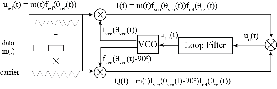
In the simplest case m^2(t) = 1. Therefore, m^2(t) = 1 does not affect the input of the noise-reduction filter. The carrier and voltage-controlled oscillator (VCO) signals are periodic oscillations f_{ref,vco}(\theta_{ref,vco}(t)) with high-frequencies \dot\theta_{ref,vco}(t). The block \bigotimes is an analog multiplier.
A linear filter can be described mathematically by a system of linear differential equations: :\begin{array}{ll} \dot x = Ax + b u_{d}(t),& u_{LF} = c^*x. \end{array} where A is a constant matrix, x(t) is a state vector of the filter, b and c are constant vectors.
The model of a VCO is usually assumed to be linear: : \begin{array}{ll} \dot\theta_{vco}(t) = \omega^{free}{vco} + K{vco} u_{LF}(t),& t \in [0,T], \end{array} where \omega^{free}{vco} is the free-running frequency of the VCO and K{vco} is the VCO gain factor. Similarly, it is possible to consider various nonlinear models of VCO.
Suppose that the frequency of the master generator is constant \dot\theta_{ref}(t) \equiv \omega_{ref}. Equation of VCO and equation of filter yield : \begin{array}{ll} \dot{x} = Ax + bf_{ref}(\theta_{ref}(t))f_{vco}(\theta_{vco}(t)),& \dot\theta_{vco} = \omega^{free}{vco} + K{vco}c^*x. \end{array}
The system is non-autonomous and rather tricky for investigation.
In the phase-frequency domain


In the simplest case, when
: \begin{align}
f_{ref}\big(\theta_{ref}(t)\big) = \cos\big(\omega_{ref} t\big),
f_{vco}\big(\theta_{vco}(t)\big) &= \sin\big(\theta_{vco}(t)\big) \
f_{ref}\big(\theta_{ref}(t)\big)^2 f_{vco}\left(\theta_{vco}(t)\right)
f_{vco}\left(\theta_{vco}(t) - \frac{\pi}{2}\right) &=
-\frac{1}{8}\Big(
2\sin(2\theta_{vco}(t)) +
\sin(2\theta_{vco}(t) - 2\omega_{ref} t) +
\sin(2\theta_{vco}(t) + 2\omega_{ref} t)
\Big)
\end{align}
The standard engineering assumption is that the filter removes the upper sideband frequency from the input but leaves the lower sideband without change. Thus it is assumed that the VCO input is \varphi(\theta_{ref}(t) - \theta_{vco}(t)) = \frac{1}{8}\sin(2\omega_{ref} t - 2\theta_{vco}(t)). This makes a Costas loop equivalent to a phase-locked loop with phase detector characteristic \varphi(\theta) corresponding to the particular waveforms f_{ref}(\theta) and f_{vco}(\theta) of the input and VCO signals. It can be proved that filter outputs in the time and phase-frequency domains are almost equal. | doi-access=free
Thus it is possible{{cite book :\begin{align} \dot{x} &= Ax + b\varphi(\Delta\theta), \ \Delta\dot{\theta} &= \omega_{vco}^{free} - \omega_{ref} + K_{vco}c^*x, \ \Delta\theta &= \theta_{vco} - \theta_{ref}. \end{align}.
The Krylov–Bogoliubov averaging method allows one to prove that solutions of non-autonomous and autonomous equations are close under some assumptions. Thus, the Costas loop block diagram in the time domain can be asymptotically changed to the block diagram on the level of phase-frequency relations.
The transition to the analysis of an autonomous dynamical model of the Costas loop (in place of the non-autonomous one) allows one to overcome the difficulties related to modeling the Costas loop in the time domain, where one has to simultaneously observe a very fast time scale of the input signals and slow time scale of signal's phase. This idea makes it possible |doi-access=free
Frequency acquisition
| [[File:Costas loop before sync.png | 340px | thumb | Costas loop before synchronization]] | [[File:Costas loop after sync.png | 290px | thumb | Costas loop after synchronization]] |
|---|
| [[File:Costas loop signals before sycnhronization.svg | 290px | thumb | Carrier and VCO signals before synchronization]] | [[File:Costas loop trainsient process.svg | 160px | thumb | VCO input during synchronization]] | [[File:Costas loop after synchronization.svg | 290px | thumb | Carrier and VCO signals after synchronization]] |
|---|
The classical Costas loop will work towards making the phase difference between the carrier and the VCO become a small, ideally zero, value. The small phase difference implies that frequency lock has been achieved.
QPSK Costas loop
The classical Costas loop can be adapted to QPSK modulation for higher data rates.{{cite patent

The input QPSK signal is as follows : m_1(t)\cos\left(\omega_\text{ref} t\right) + m_2(t)\sin\left(\omega_\text{ref} t\right), m_1(t) = \pm 1, m_2(t) = \pm 1.
Inputs of low-pass filters LPF1 and LPF2 are :\begin{align} \varphi_1(t) &= \cos\left(\theta_\text{vco}\right)\left(m_1(t)\cos\left(\omega_\text{ref} t\right) + m_2(t)\sin\left(\omega_\text{ref} t\right)\right), \ \varphi_2(t) &= \sin\left(\theta_\text{vco}\right)\left(m_1(t)\cos\left(\omega_\text{ref} t\right) + m_2(t)\sin\left(\omega_\text{ref} t\right)\right). \end{align}
After synchronization, the outputs of LPF1 Q(t) and LPF2 I(t) are used to get demodulated data (m_1(t) and m_2(t)). To adjust the frequency of the VCO to the reference frequency, signals Q(t) and I(t) are limited and cross-multiplied: :u_d(t) = I(t)\sgn(Q(t)) - Q(t)\sgn(I(t)).
Then the signal u_d(t) is filtered by the loop filter and forms the tuning signal for the VCO u_\text{LF}(t), similar to BPSK Costas loop. Thus, QPSK Costas can be described :\begin{align} \dot{x}1 &= A\text{LPF} x_1 + b_\text{LPF}\varphi_1(t),\ \dot{x}2 &= A\text{LPF} x_2 + b_\text{LPF}\varphi_2(t),\ \dot{x} &= A_\text{LF} x + b_\text{LF}\big(c_\text{LPF}^* x_1\sgn(c_\text{LPF}^* x_2) - c_\text{LPF}^* x_2\sgn(c_\text{LPF}^* x_1)\big),\ \dot{\theta}\text{vco} &= \omega\text{vco}^\text{free} + K_\text{VCO}\Big(c^\text{LF} x + h\text{LF}\big(c_\text{LPF}^ x_1\sgn(c_\text{LPF}^* x_2) - c_\text{LPF}^* x_2\sgn(c_\text{LPF}^* x_1)\big)\Big).\ \end{align}
Here A_\text{LPF}, b_\text{LPF}, c_\text{LPF} are parameters of LPF1 and LPF2 and A_\text{LF}, b_\text{LF}, c_\text{LF}, h_\text{LF} are parameters of the loop filter.
References
References
- Costas, John P.. (August 2002). "Synchronous Communications". Proceedings of the IEEE.
- (2010). "Communication Systems". John Wiley & Sons, Inc..
- {{harvnb. Costas. 1956 states, "The local oscillator must be maintained at proper phase so that the audio output contributions of the upper and lower sidebands reinforce one another. If the oscillator phase is 90° away from the optimum value, a null in audio output will result, which is typical of detectors of this type. The actual method of phase control will be explained shortly, but for the purpose of this discussion, maintenance of correct oscillator phase shall be assumed."
- Using a loop filter with an integrator allows a steady-state phase error of zero. See {{section link. PID controller. Integral term.
- Best, Roland E.. (1997). "Phase-Locked Loops". McGraw-Hill.
This article was imported from Wikipedia and is available under the Creative Commons Attribution-ShareAlike 4.0 License. Content has been adapted to SurfDoc format. Original contributors can be found on the article history page.
Ask Mako anything about Costas loop — get instant answers, deeper analysis, and related topics.
Research with MakoFree with your Surf account
Create a free account to save articles, ask Mako questions, and organize your research.
Sign up freeThis content may have been generated or modified by AI. CloudSurf Software LLC is not responsible for the accuracy, completeness, or reliability of AI-generated content. Always verify important information from primary sources.
Report