From Surf Wiki (app.surf) — the open knowledge base
Dislocation
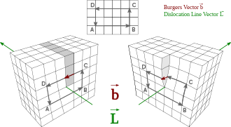
Linear crystallographic defect or irregularity
In materials science, a dislocation is a linear crystallographic defect or irregularity within a crystal structure that contains an abrupt change in the arrangement of atoms. The movement of dislocations allows atoms to slide over each other at low stress levels and is known as glide or slip. The crystalline order is restored on either side of a glide dislocation but the atoms on one side have moved by one position. The crystalline order is not fully restored with a partial dislocation. A dislocation defines the boundary between slipped and unslipped regions of material and as a result, must either form a complete loop, intersect other dislocations or defects, or extend to the edges of the crystal. A dislocation can be characterised by the distance and direction of movement it causes to atoms which is defined by the Burgers vector. Plastic deformation of a material occurs by the creation and movement of many dislocations. The number and arrangement of dislocations influences many of the properties of materials.
The two primary types of dislocations are sessile dislocations which are immobile and glissile dislocations which are mobile. Examples of sessile dislocations are the stair-rod dislocation and the Lomer–Cottrell junction. The two main types of mobile dislocations are edge and *screw * dislocations.
Edge dislocations can be visualized as being caused by the termination of a plane of atoms in the middle of a crystal. In such a case, the surrounding planes are not straight, but instead bend around the edge of the terminating plane so that the crystal structure is perfectly ordered on either side. This phenomenon is analogous to half of a piece of paper inserted into a stack of paper, where the defect in the stack is noticeable only at the edge of the half sheet.
Screw dislocations create faults in a crystal that looks similar to that of a spiral staircase. These types of dislocations can be formed by cutting halfway through a crystal and sliding those regions on each side of the cut parallel to the cut to create spiraling atom planes. The dislocation line would be located in the central axis of the spiral.
The theory describing the elastic fields of the defects was originally developed by Vito Volterra in 1907. In 1934, Egon Orowan, Michael Polanyi and G. I. Taylor, proposed that the low stresses observed to produce plastic deformation compared to theoretical predictions at the time could be explained in terms of the theory of dislocations.
History
The theory describing the elastic fields of the defects was originally developed by Vito Volterra in 1907. The term 'dislocation' referring to a defect on the atomic scale was coined by G. I. Taylor in 1934.
Prior to the 1930s, one of the enduring challenges of materials science was to explain plasticity in microscopic terms. A simplistic attempt to calculate the shear stress at which neighbouring atomic planes slip over each other in a perfect crystal suggests that, for a material with shear modulus G, shear strength \tau_m is given approximately by:
:: \tau_m = \frac {G} {2 \pi}.
The shear modulus in metals is typically within the range 20 000 to 150 000 MPa indicating a predicted shear stress of 3 000 to 24 000 MPa. This was difficult to reconcile with measured shear stresses in the range of 0.5 to 10 MPa.
In 1934, Egon Orowan, Michael Polanyi and G. I. Taylor, independently proposed that plastic deformation could be explained in terms of the theory of dislocations. Dislocations can move if the atoms from one of the surrounding planes break their bonds and rebond with the atoms at the terminating edge. In effect, a half plane of atoms is moved in response to shear stress by breaking and reforming a line of bonds, one (or a few) at a time. The energy required to break a row of bonds is far less than that required to break all the bonds on an entire plane of atoms at once. Even this simple model of the force required to move a dislocation shows that plasticity is possible at much lower stresses than in a perfect crystal. In many materials, particularly ductile materials, dislocations are the "carrier" of plastic deformation, and the energy required to move them is less than the energy required to fracture the material.
Mechanisms
A dislocation is a linear crystallographic defect or irregularity within a crystal structure which contains an abrupt change in the arrangement of atoms. The crystalline order is restored on either side of a dislocation but the atoms on one side have moved or slipped. Dislocations define the boundary between slipped and unslipped regions of material and cannot end within a lattice and must either extend to a free edge or form a loop within the crystal. A dislocation can be characterised by a vector comprising the distance and direction of relative movement it causes to atoms as it moves through the lattice. This characterising vector is called the Burgers vector and remains constant even though the shape of the dislocation may change or deform.
A variety of dislocation types exist, with mobile dislocations known as glissile and immobile dislocations called sessile. The movement of mobile dislocations allow atoms to slide over each other at low stress levels and is known as glide or slip. The movement of dislocations may be enhanced or hindered by the presence of other elements within the crystal and over time, these elements may diffuse to the dislocation forming a Cottrell atmosphere. The pinning and breakaway from these elements explains some of the unusual yielding behavior seen with steels. The interaction of hydrogen with dislocations is one of the mechanisms proposed to explain hydrogen embrittlement.
Dislocations behave as though they are a distinct entity within a crystalline material where some types of dislocation can move through the material bending, flexing and changing shape and interacting with other dislocations and features within the crystal. Dislocations are generated by deforming a crystalline material such as metals, which can cause them to initiate from surfaces, particularly at stress concentrations or within the material at defects and grain boundaries. The number and arrangement of dislocations give rise to many of the properties of metals such as ductility, hardness and yield strength. Heat treatment, alloy content and cold working can change the number and arrangement of the dislocation population and how they move and interact in order to create useful properties.
Generating dislocations
When metals are subjected to cold working (deformation at temperatures which are relatively low as compared to the material's absolute melting temperature, T_m i.e., typically less than 0.4T_m) the dislocation density increases due to the formation of new dislocations. The consequent increasing overlap between the strain fields of adjacent dislocations gradually increases the resistance to further dislocation motion. This causes a hardening of the metal as deformation progresses. This effect is known as strain hardening or work hardening.
Dislocation density \rho in a material can be increased by plastic deformation by the following relationship:
::\tau \propto \sqrt{\rho}.
Since the dislocation density increases with plastic deformation, a mechanism for the creation of dislocations must be activated in the material. Three mechanisms for dislocation formation are homogeneous nucleation, grain boundary initiation, and interfaces between the lattice and the surface, precipitates, dispersed phases, or reinforcing fibers.
Homogeneous nucleation
The creation of a dislocation by homogeneous nucleation is a result of the rupture of the atomic bonds along a line in the lattice. A plane in the lattice is sheared, resulting in 2 oppositely faced half planes or dislocations. These dislocations move away from each other through the lattice. Since homogeneous nucleation forms dislocations from perfect crystals and requires the simultaneous breaking of many bonds, the energy required for homogeneous nucleation is high. For instance, the stress required for homogeneous nucleation in copper has been shown to be \frac {\tau_{\text{hom}}}{G}=7.4\times10^{-2}, where G is the shear modulus of copper (46 GPa). Solving for \tau_{\text{hom}} ,!, we see that the required stress is 3.4 GPa, which is very close to the theoretical strength of the crystal. Therefore, in conventional deformation homogeneous nucleation requires a concentrated stress, and is very unlikely. Grain boundary initiation and interface interaction are more common sources of dislocations.
Irregularities at the grain boundaries in materials can produce dislocations which propagate into the grain. The steps and ledges at the grain boundary are an important source of dislocations in the early stages of plastic deformation.
Frank–Read source
Main article: Frank–Read source
The Frank–Read source is a mechanism that is able to produce a stream of dislocations from a pinned segment of a dislocation. Stress bows the dislocation segment, expanding until it creates a dislocation loop that breaks free from the source.
Surfaces
The surface of a crystal can produce dislocations in the crystal. Due to the small steps on the surface of most crystals, stress in some regions on the surface is much larger than the average stress in the lattice. This stress leads to dislocations. The dislocations are then propagated into the lattice in the same manner as in grain boundary initiation. In single crystals, the majority of dislocations are formed at the surface. The dislocation density 200 micrometres into the surface of a material has been shown to be six times higher than the density in the bulk. However, in polycrystalline materials the surface sources do not have a major effect because most grains are not in contact with the surface.
Interfaces
The interface between a metal and an oxide can greatly increase the number of dislocations created. The oxide layer puts the surface of the metal in tension because the oxygen atoms squeeze into the lattice, and the oxygen atoms are under compression. This greatly increases the stress on the surface of the metal and consequently the amount of dislocations formed at the surface. The increased amount of stress on the surface steps results in an increase in dislocations formed and emitted from the interface.
Dislocations may also form and remain in the interface plane between two crystals. This occurs when the lattice spacing of the two crystals do not match, resulting in a misfit of the lattices at the interface. The stress caused by the lattice misfit is released by forming regularly spaced misfit dislocations. Misfit dislocations are edge dislocations with the dislocation line in the interface plane and the Burgers vector in the direction of the interface normal. Interfaces with misfit dislocations may form e.g. as a result of epitaxial crystal growth on a substrate.
Irradiation
Dislocation loops may form in the damage created by energetic irradiation. A prismatic dislocation loop can be understood as an extra (or missing) collapsed disk of atoms, and can form when interstitial atoms or vacancies cluster together. This may happen directly as a result of single or multiple collision cascades, which results in locally high densities of interstitial atoms and vacancies. In most metals, prismatic dislocation loops are the energetically most preferred clusters of self-interstitial atoms.
Interaction and arrangement
Geometrically necessary dislocations
Main article: Geometrically necessary dislocations
Geometrically necessary dislocations are arrangements of dislocations that can accommodate a limited degree of plastic bending in a crystalline material. Tangles of dislocations are found at the early stage of deformation and appear as non well-defined boundaries; the process of dynamic recovery leads eventually to the formation of a cellular structure containing boundaries with misorientation lower than 15° (low angle grain boundaries).
Pinning
Adding pinning points that inhibit the motion of dislocations, such as alloying elements, can introduce stress fields that ultimately strengthen the material by requiring a higher applied stress to overcome the pinning stress and continue dislocation motion.
The effects of strain hardening by accumulation of dislocations and the grain structure formed at high strain can be removed by appropriate heat treatment (annealing) which promotes the recovery and subsequent recrystallization of the material.
The combined processing techniques of work hardening and annealing allow for control over dislocation density, the degree of dislocation entanglement, and ultimately the yield strength of the material.
Persistent slip bands
Main article: Persistent slip bands
Repeated cycling of a material can lead to the generation and bunching of dislocations surrounded by regions that are relatively dislocation free. This pattern forms a ladder like structure known as a persistent slip bands (PSB). PSB's are so-called, because they leave marks on the surface of metals that even when removed by polishing, return at the same place with continued cycling.
PSB walls are predominately made up of edge dislocations. In between the walls, plasticity is transmitted by screw dislocations.
Where PSB's meet the surface, extrusions and intrusions form, which under repeated cyclic loading, can lead to the initiation of a fatigue crack.
Movement
Main article: Dislocation creep
Glide
Main article: Slip (materials science)
Dislocations can slip in planes containing both the dislocation line and the Burgers vector, the so called glide plane. For a screw dislocation, the dislocation line and the Burgers vector are parallel, so the dislocation may slip in any plane containing the dislocation. For an edge dislocation, the dislocation and the Burgers vector are perpendicular, so there is one plane in which the dislocation can slip.
Climb
Dislocation climb is an alternative mechanism of dislocation motion that allows an edge dislocation to move out of its slip plane. The driving force for dislocation climb is the movement of vacancies through a crystal lattice. If a vacancy moves next to the boundary of the extra half plane of atoms that forms an edge dislocation, the atom in the half plane closest to the vacancy can jump and fill the vacancy. This atom shift moves the vacancy in line with the half plane of atoms, causing a shift, or positive climb, of the dislocation. The process of a vacancy being absorbed at the boundary of a half plane of atoms, rather than created, is known as negative climb. Since dislocation climb results from individual atoms jumping into vacancies, climb occurs in single atom diameter increments.
During positive climb, the crystal shrinks in the direction perpendicular to the extra half plane of atoms because atoms are being removed from the half plane. Since negative climb involves an addition of atoms to the half plane, the crystal grows in the direction perpendicular to the half plane. Therefore, compressive stress in the direction perpendicular to the half plane promotes positive climb, while tensile stress promotes negative climb. This is one main difference between slip and climb, since slip is caused by only shear stress.
One additional difference between dislocation slip and climb is the temperature dependence. Climb occurs much more rapidly at high temperatures than low temperatures due to an increase in vacancy motion. Slip, on the other hand, has only a small dependence on temperature.
Dislocation avalanches
Main article: Dislocation avalanches
Dislocation avalanches occur when multiple simultaneous movement of dislocations occur.
Dislocation Velocity
Dislocation velocity is largely dependent upon shear stress and temperature, and can often be fit using a power law function:
\mathbf{f} = \mathbf{F} \times \mathbf{s} = \begin{vmatrix} \hat\imath & \hat\jmath & \hat k \ F_x & F_y & F_z \ s_x & s_y & s_z \end{vmatrix}
The components of the stress field can be obtained from the Burgers vector, normal stresses, \sigma, and shear stresses, \tau.
::\begin{aligned} F_x &= b_x\sigma_{xx} + b_y\tau_{xy} + b_z\tau_{xz} \ F_y &= b_x\tau_{yx} + b_y\sigma_{yy} + b_z\tau_{yz} \ F_z &= b_x\tau_{zx} + b_y\tau_{zy} + b_z\sigma_{zz} \end{aligned}
Forces between dislocations
The force between dislocations can be derived from the energy of interactions of the dislocations, U_{\rm int}. The work done by displacing cut faces parallel to a chosen axis that creates one dislocation in the stress field of another displacement. For the x and y directions:
::\begin{aligned} U_{\rm int} &= \int_{x}^{\infty} (b_x\tau_{xy} + b_y\sigma_{yy} + b_z\sigma_{zy}), dx \ U_{\rm int} &= \int_{y}^{\infty} (b_x\sigma_{xx} + b_y\tau_{yx} + b_z\sigma_{zx}), dy \end{aligned}
The forces are then found by taking the derivatives.
::\begin{aligned} F_x &= - \frac{\partial U_{\rm int}}{\partial x} \ F_y &= - \frac{\partial U_{\rm int}}{\partial y} \end{aligned}
Free surface forces
Dislocations will also tend to move towards free surfaces due to the lower strain energy. This fictitious force can be expressed for a screw dislocation with the y component equal to zero as:
Ask Mako anything about Dislocation — get instant answers, deeper analysis, and related topics.
Research with MakoFree with your Surf account
Create a free account to save articles, ask Mako questions, and organize your research.
Sign up freeThis content may have been generated or modified by AI. CloudSurf Software LLC is not responsible for the accuracy, completeness, or reliability of AI-generated content. Always verify important information from primary sources.
Report